The building services coordination is often a crucial and challenging task in complex construction projects. The traditional 2D based MEP coordination process starts, once the individual MEP services systems have been designed and the routings are being largely determined. The MEP coordination process entail by overlaying various discipline drawings (shop drawings of the same scale from different contractors) using a light table and manually checking for any conflicts among the services. This manual process has proven to be time-consuming and brings in a lot of errors and reworks.
When CAD was introduced back in 1957, the 2D process has become a bit more efficient but the problem persists as there was a high degree of intuition, technical knowledge, experience in project execution, and imagination required to identify and mitigate the clashes found.
And later an era of BIM Coordination started, where interdisciplinary coordination happens in a virtual environment.
Challenges in 2D MEP Coordination
- No automated system to identify clashes.
- Difficulty in visualizing clashes as this mostly relay on imagination of the reviewer.
- Coordinating complex projects require additional resource and time as the process may require long number of multiple sections to coordinate the congested spaces.
- Understanding the impact on other services for a change in coordination or routing is quite a complicated task. E.g., If the main fire pipe is raised by 100mm in the corridor, it’s an exhaustive task to identify the impact it makes on other services in the long run.
- It’s a cumbersome process to repeat the 2D MEP coordination process in-case of design or procurement-led changes.
- The process does not guarantee a clash free drawing, because of overlaying the drawings over one another and identifying the clashes is an exhaustive process and its highly prone to human errors, which makes its inability to deliver a clash free drawing for site execution.
- The accuracy of the information provided on a CAD drawing is questionable as the information shown in drawings is not attached with the objects drawn. E.g., A duct drawn with a width of 200mm can be labelled as 250mm.
Impact of 2D MEP Coordination Process
- Understanding the impact of all building services systems, structural and architectural elements that may impede or impact a system or service route.
- Increase in number of RFI’s (Request for Information) and Change Orders due to the identification on issues during site execution.
- Reduction in Offsite Fabrication as there is always an uneasiness among coordinators that there might be changes or rework happening in site as a part of coordination.
- Any potential unresolved clash identified while on site execution may affect the planned construction schedule. This may also lead to budget overrun.
- Added number of issues identified on-site may affect the overall productivity of a project.
BIM based MEP Coordination Process
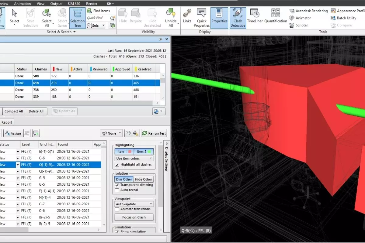
The BIM Coordination process using a 3D model has become a game changer by providing us a virtual platform to investigate the potential clashes that may occur during site execution. The automated process of clash identification using tools like Autodesk Navisworks or Solibri Model Checker has improved the speed of coordination as well lowered the time to mitigate the clashes found.
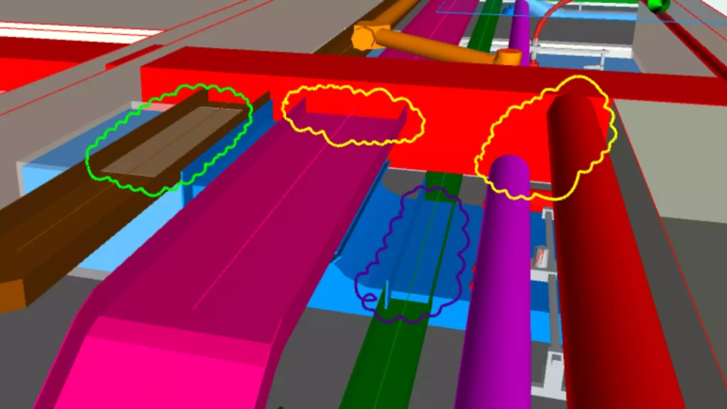
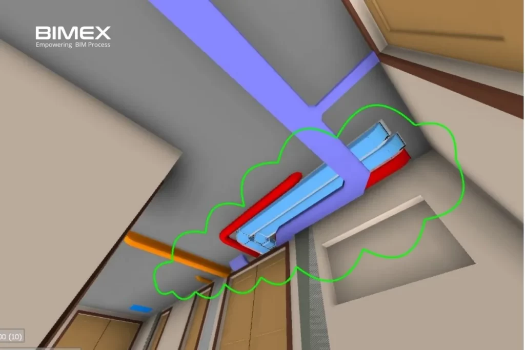
Clash reports can be generated by software itself for better clarity. Identified clashes can be corrected during coordination or can be raised to the design review team as RFI’s.
Early identification of clashes can avoid rework and wastage of materials due to onsite coordination.
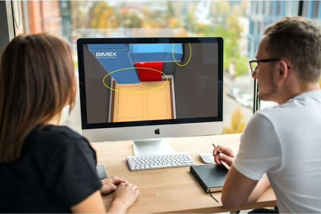
The BIM coordination has brought in a collaborative approach where stakeholders from different trades can communicate, and issues can be resolved based on the priorities. This has simplified the coordination process, bringing in more time and cost-savings.
The paramount advantage of using a 3D Model based coordination is its ability to involve the trade contractors in the earlier stages of the coordination process, likewise the coordination can be start from the design development stage.
Typical 3D MEP BIM Coordination Process
The collaborative nature of the BIM Coordination Process has the ability to communicate the project quickly and easily by providing 3D visuals that resembles to the final service installation. A typical M&E coordination process can be defined as follows:
- The process is initiated by creating a spatial zoning for the design and there after the trade wise modelling of HVAC, piping, plumbing, fire protection and electrical services.
- Architecture and structural models are linked for modelling the M&E services without any clashes.
- Clashes can be easily identified once the complete model is in place.
- Software like Autodesk Navisworks or Solibri Model Checker can be used for walk-through through the model and can also be used to identify and document interdisciplinary clashes.
- Clashes found are resolved during BIM Coordination workshops.
- Identified clashes can be easily tracked in review stage through Specific Viewpoints and can be used in future project as references.
- Drawing generation starts once the model is interference free.
- 3D Software platforms like Autodesk Revit allows the creation of sections at any areas directly from the model.
- The use of intelligent 3D modelling software assure that the labels are taken directly from the 3D model, with no chance that the services being modelled as one size and tagged as another.
The BIM coordination is a cyclic process that can be initiated right from the start of a project. Several iterations of clash detection and coordination workshops are held to resolve potential clashes and design errors before the design being finalized for site execution.
Conclusion
Apart from Coordination, the BIM approach has got numerous benefits like AR/VR which is real time visualisation on Building Model, accurate quantity estimation, intelligent drawings generation, prefabrication, energy analysis, facility management etc. The use of traditional 2D MEP Coordination process lacks accurate interference checking capability and may result in coordination issues, rework, material wastage, cost overrun, delay etc. whereas the BIM based coordination approach has proven to be more efficient and is found to be the preferred method for MEP coordination.
